Thursday, January 2, 2020

Horizontal Stab 4... Finished! (Time: 60 hours)

Horizontal Stab 4...


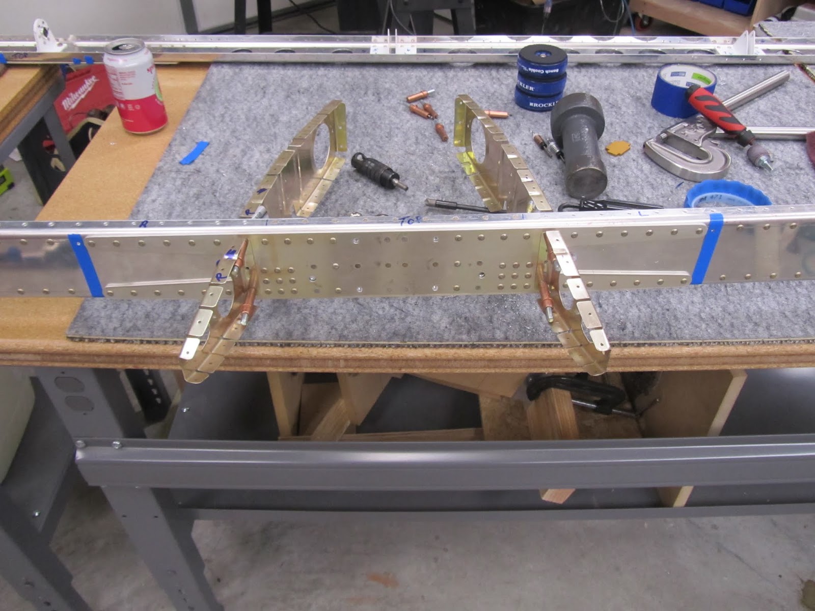
Once the rear spar was primed, it got cleco'd into position. 

I'm not going to assume the readers of this blog know the intricate details of aircraft sheetmetal work, so I will try to explain the next problem I had to solve. Remember, the holes on the spar are all countersunk, and the skins are dimpled. What that means is that when you drill a #40 hole, you are drilling a hole that is .0985". That is the typical size hole that is drilled for a 3/32" rivet (which is only .09375")

Nearly every sheetmetal hole on a Van's aircraft is dimpled, and this in turn slightly expands that #40 (.0985") hole to some degree. The net affect is that the average "Cleco-Loc USA" cleco's, do not hold. They will hold in place, but once you buck a rivet nearby, they shoot out of the piece by themselves. I got tired of chasing cleco's around my shop and decided to solve the issue.

I called the folks at CLEVELAND AIRCRAFT TOOL and as always, they were a wealth of knowledge. I explained the problem, and they indicated their brand of cleco's (called Wedge-Loc) would indeed hold on a #40 dimpled hole. I think I ordered 125 of them (5 bags), and tried them out. They worked as advertised! Seriously, they are rock solid, so I ordered 5 additional bags, for a total of 250 of the wedge-loc cleco's. To keep them separate from the other type clecos, I had my son lay out some butcher paper and spray paint all of them red. The paint absolutely does not effect the operation at all...

LINK: Cleco's that work with dimpled holes

My son was there to help when the cleco's would fly, but I was determined to find a solution!

IKEA cart for holding my rivet stuff... Very handy...


 Here you can see the new "Wedge-Loc" cleco's from Cleveland Aircraft Tool. I cannot say enough great stuff about them!

Also, I like to use green "Frog Tape" when working around the lightening holes on the HS. I didnt want to have my super heavy tungsten bucking bar fall into a hole, and make a dent. The tape also helps prevent scratches in the alclad.


This guy is the best assistant in the world.

The rivets holding the inspar ribs to the spar were extremely stressful. Just make sure you have a 12" long AN470 rivet set, and a huge angled bucking bar. Don't slip, because you are driving directly into the spar truss.... (sweating bullets...)

Eventually I finished. I touched up the paint and moved on.


TAHH DAHHH!!!! The horizontal stab is finished. I was very pleased with how it turned out. It's very satisfying to see something that looks like an airplane part...


I built a wall mount to free up the space in the garage. Nothing fancy, just enough to hold it secure, up and out of the way.

Just a couple of gate handles, velcro straps, and some huge zip-ties, just in case.


I learned a lot while completing the HS. Most of all, I learned to take my time, and don't rush. Everyone always says this, but it's so easy to fall into the "I think I know what the plans say here..." instead of going over and rereading the plans again. 

Additionally, I feel that I learned a great deal about having the correct tool for the job. No matter what you do, if you have the wrong tool, you are going to screw something up. If you want to go cheap, you are going to get cheap results. Get the right tool, and you will thank yourself for it. 

On to the elevators!

Horizontal Stab 3...

Horizontal Stab 3...

Things start to come together pretty quick at this point on the HS. I like to use the blue vinyl tape to remind myself of things that should, or should not be done.


You keep adding ribs and making sure everything fits. The nose ribs on the ends of the fwd spar get added pretty early on.

You can see the shape of the inspar ribs, that identify where the aft fuselage will sit.


Next was adding the nose ribs to the skins on the HS. This is harder than it sounds, because there is no great way to get a bucking bar into place, and also the very tight angle of the leading edge. I had to be VERY careful when driving the flush rivets. With a flush rivet set, and a round leading edge, I war paranoid about making dents etc. This process is done with your arms extended into the skins, it's not really fun, but it got done. 


Next: After the nose ribs are riveted in place, I put everything together and verified the fit. Once satisfied, it all gets disassembled, and I decided to prime the entire assembly. With most parts being alclad, I do not believe everything needs primer, however, it was easy enough to do, and I wanted the practice.


The primer was purchased at Advanced Aircraft Coatings in Oklahoma City. They were HIGHLY knowledgeable about the products, and helped me with some "first timer" details. They saved me some bucks too, which I certainly appreciate!

Anywhoo, so, I set up my handy dandy PVC spray rack, and laid down some butcher paper to help with the overspray. I donned my respirator, gloves, and face shield, and sprayed the HS, and the inside of the skins. It turned out great. 

I chose a fairly inexpensive set of paint guns I found on Amazon (They can be found here) for a few reasons. 1) I am just spraying primer, and not painting a car, so I do not need a crazy fancy HVLP set up. 2) this set came with three different sizes of spray guns, which has proven to be very handy. 3) I wanted a set of guns I could learn to spray with, and for less than $100.00 this set was perfect.

Spraying primer is not very tough at all. Once you figure out the fact that there is a balance between the airflow, and the amount of paint you are sending down to the parts. I would rather make multiple passes than have something run, so I sprayed pretty light.

Cleanup was very easy. Just spray some acetone through the gun, and was up all the hard parts with acetone as well. Spraying primer was a great learning experience.


A couple of days later, I got tired of the terrible fall weather here in Oklahoma, and I decided I wanted to prime the inside of the rear spar. I had a BUNCH of plastic left over from painting our living room, so I put it to good use. You can see below to the right in this photo that the fwd spar assembly had been riveted in to place.


Wednesday, January 1, 2020

Horizontal Stab 2...

Horizontal Stab 2...

Here you can start to see the fwd and rear spars coming together. The plans go to great lengths to describe small bends that go into the flanges for the nose ribs that are adjacent to the inside inspar ribs. You can start to see the aft shape of the fuselage here. 

I didn't get too worked up about being a degree or two off, because the entire assembly kinda moves around until its all riveted together. The stressful thing was drilling through the spars. Make sure you have your poop in a group before you hit the drill trigger!


Like I said, things progressed, and this part of the build was actually pretty enjoyable. Lots of setting up, drilling, then disassembly for deburring etc.


I forgot to mention: both spars have about a zillion countersinks top and bottom. Even with a new cutter, and a countersink tool with excellent bearings, I was still getting some chatter. Ended up, I had to hold a piece of material beneath the flange of the spar, with a #40 hole for the guide on the cutter. This eliminated the chatter all together.

Note the tape on the top of the spar truss. That is personal preference only. I didn't like how the chips were getting down in between/behind the truss, so tap prevents it.
  Countersink, countersink, and countersink some more.


I dont remember what this assembly is called, but it starts coming together quick.


Inspar ribs get attached, and then cleco to the fwd spar. match drilled, and then deburred.

You can start to see how clamping parts helps keep things in one place. I found these black 90 degree brackets at Rockler last year. I plan on ordering more, because they are just handy as all get out. I cannot believe how much I have used them in this build already.


Horizontal Stab 1...

Horizontal Stab 1...
After dealing with the problems on the rudder tailing edge, I was definitely looking forward to starting the horizontal stab. It's the first piece where you begin to get an idea of the size of the plane. You begin working on the spars first. Very easy and straightforward. Both have large doublers, but the fwd spar has a much larger doubler, and caps on the top and bottom flanges. 


Rear spar getting set up. Hinges held in position, and ready to be match drilled.


This is a shot of the upper spar cap being placed before drilling.... which I screwed up. The layout is easy, and well spelled out in the manual. The spar cap piece itself is somewhat bowed when it arrives. Obviously, its not a piece you can "flute" to straighten, so, for the most part you have to just clamp it into position, and start the match drilling. I used what I thought was a lot of clamps, but I still screwed it up. 

As near as I can figure, I think one of my spring cleco clamps prevented the C-clamps from being able to drive the spar cap flush with the web of the spar.

It is not the best pic, but you can just barely see a small gap between the spar web, and the back of the spar cap in this pic. It was enough to make all of the holes incorrect. No worries though, because ordering a new spar cap is cheap, a new spar? not so much.


A few days later, the new spar cap arrived, and we were back to the build. (son in pic :-)

This time I double and triple checked the alignment of the part. I clamped it better, and it went in quick.


Rudder 5... Finished! (Time: 45 hours)

So this will sound like I'm beating on Van's a little bit, but hear me out. As I said earlier in a previous post, Van's engineering is incredible, however, I believe the trailing edge construction technique needs to be changed. After the airplane is completed, I may go back and build a new rudder, using structural adhesive on the trailing edge. I am that pissed off with how this turned out. I have looked at other RV14's, and other RV10's, and they look pretty similar to how mine turned out. I'm not a perfectionist, but the trailing edge of the rudder could be done in a different manner, that yields better results. It is nearly impossible to arrive with a trailing edge that is straight. If you drive the rivets with a gun, all it takes is one extra tap to bow that trailing edge wedge. If you use a squeezer, it seems to be impossible to get the angle correct, so you end up with small dents/imperfections in the skin. I fully realize these can be painted over, but it's just not a great technique. As stated before. I will probably rebuild this part after the plane is complete, and I will finish the trailing edge with structural adhesive. (rant over)

Ok, so here it is... Originally, I thought I would attempt to rivet against the back-rivet plate, but that turned out to be impossible. So the only method that worked was turning the rudder vertical.

 This manner didn't work because the cleco's got in the way...

Turned in this position, it was fairly to be precise with the bar and gun, but holy mother of god, trying to get it to some out straight is impossible. 

This is what it looked like after all of the rivets were done. (yeah, I was not pleased...) If there is anyone out there that has mastered this trailing edge technique, I'd love to hear from you!
 This photo is after quite a bit of "massaging" with a straight edge, and light taps with the bucking bar and gun. Like I said, I will probably rebuild it, when I have the time, and it won't slow down the project...
 BEHOLD!!!! The rudder in all of it's finished glory....


Horizontal stab coming next...