Wednesday, January 1, 2020

Rudder 5... Finished! (Time: 45 hours)

So this will sound like I'm beating on Van's a little bit, but hear me out. As I said earlier in a previous post, Van's engineering is incredible, however, I believe the trailing edge construction technique needs to be changed. After the airplane is completed, I may go back and build a new rudder, using structural adhesive on the trailing edge. I am that pissed off with how this turned out. I have looked at other RV14's, and other RV10's, and they look pretty similar to how mine turned out. I'm not a perfectionist, but the trailing edge of the rudder could be done in a different manner, that yields better results. It is nearly impossible to arrive with a trailing edge that is straight. If you drive the rivets with a gun, all it takes is one extra tap to bow that trailing edge wedge. If you use a squeezer, it seems to be impossible to get the angle correct, so you end up with small dents/imperfections in the skin. I fully realize these can be painted over, but it's just not a great technique. As stated before. I will probably rebuild this part after the plane is complete, and I will finish the trailing edge with structural adhesive. (rant over)

Ok, so here it is... Originally, I thought I would attempt to rivet against the back-rivet plate, but that turned out to be impossible. So the only method that worked was turning the rudder vertical.

 This manner didn't work because the cleco's got in the way...

Turned in this position, it was fairly to be precise with the bar and gun, but holy mother of god, trying to get it to some out straight is impossible. 

This is what it looked like after all of the rivets were done. (yeah, I was not pleased...) If there is anyone out there that has mastered this trailing edge technique, I'd love to hear from you!
 This photo is after quite a bit of "massaging" with a straight edge, and light taps with the bucking bar and gun. Like I said, I will probably rebuild it, when I have the time, and it won't slow down the project...
 BEHOLD!!!! The rudder in all of it's finished glory....


Horizontal stab coming next...

Rudder 4...

Rudder 4...

Up to this point, this has been my favorite part of the build. I really enjoy back riveting. Its all very straightforward. I bought a machined flat steel plate from a machine shop. It's about 18" long, and 5"? wide? It's .5" thick, and it works PERFECT for back riveting. 

 -3 rivets when completed...


All of the "914" brackets to the right hand side are riveted with "pop" rivets. I was considering replacing that fastener with "cherry-max" type, but OH BOY am I glad I did not. (pics to come)


I used some old 18 gauge wire strung up over my garage door opener to hold the rudder skin while riveting the 914 brackets into position. The coating on the wire worked perfect as it didn't mar the skin. 


Here is where things went a little sideways. You have to pay particular attention to how the ribs lay over the brackets. Somewhere in the middle of the process, I got the order wrong, and had to drill out about 8 of the LP 4-3 pop-rivets. If those would have been cherry-max, I would have been screwed. As it was, the only way I could reach those pop-rivets, was with a 90 degree drill.

I believe this was the first one I screwed up? In any case, pay attention to the directions, and go slow....

So this is just a post about technique, but I thought I'd throw it in anyways. Note the four rivets on the bottom of the rudder horn: those were probably the most stressful rivets to drive thus far in the build. The rudder horn is thick, and the R910 bracket proveides a challenge for access etc. Here is how I did it. Others might have a much better method, but this worked for me?

I use these padded envelopes that come with Amazon packages. They work great at protecting sheetmetal while the bucking bar bounces around. 

This is 3M vinyl tape. It came like this in the mail. Maybe the roll got too hot at some point?

This is the little pad that I made to hold the bucking bar "up" because my fingers were just a little too big.

You can see that I didn't want the bucking bar hitting that nut plate thingy... Anywhoo, this is my technique, you might come up with something better!


So, onward and upward. you rivet all the skin to the rudder spar, and its super easy. Work progressed quickly up until I realized I had drilled the wrong holes in the "counterbalance-rib" thingy? The pic below shows it in the incorrect position. It's difficult to see, but the rib looks almost symmetrical, but it is not. You drill the holes long before its installed in the spar, and by then it's too late. Oh well, I just called Van's, and they said drill new holes and build on. No reason to replace it. (thank goodness))  


The corrected counterbalance installed. Be careful, its easy to over tighten the bolts that hold it in place. 


The work progressed on riveting the skin. Some of the time, you have to think out of the box. My hands didn't fit, So I had to tape the bucking bar to this stick for a few rivets. It worked surprisingly well. 

 The rivets near the trailing edge are almost impossible to access. Even with the foot on this bar, they were very difficult. I taped two bars together for some extra mass.

To be continued.....


Rudder 3...

As the rudder started to come together, it became very evident that holding the pieces down was going to become extra important. I was able to fashion some wood blocks to sandwich the rudder spar. Then I clamped those pieces to the work surface. That worked pretty well. Once I started working with the skins, I had to modify just a bit.

 This worked well initially. Especially when driving the rivets for that rudder horn (the thick machined part at the bottom)
Various doubles and nut plates get installed to attach the rudder. Simple...
 This is when the rudder really starts to take shape. It went together VERY easy...


I prefer to label all of my parts with a sharpie. It keeps it straight in my mind... Your mileage mar vary...
 Then, it happened... I realized I screwed up the hole for the rudder counterbalance. See the two dimpled holes on the bottom? they are supposed to be on top. (whoops). I called vans and they said just punch a new hole, dimple, then build on. Lesson learned, look at the part depiction in the instructions ten times before drilling...

Next, there was a brace at the bottom of the rudder horn that required some massaging. Its kind of hard to see in the pics, but the part labeled R910, did not sit flush with the rudder horn. But, because it is riveted on the front, both sides, and the bottom (to the horn), you better make sure the part fits perfects before banging away. I lined up the part in the skin ribs, and then the web adjacent to the skin ribs, and discovered some "massaging" needed to be done where the part hit the rudder horn. Using a hand seamer, I carefully adjusted the radius on the tab that extends to the rudder horn. It fit perfectly, it just took some time. 

The next magic trick came when tyring to buck the -4 rivets behind that R910 gusset/bracket. I strongly urge you to use padded envelope material that is cut to fit. If not, the bucking bar will make a mess back there. I also used a tungsten bar, I have no idea how a steel bar would perform in such a small area. 

Before the R910...
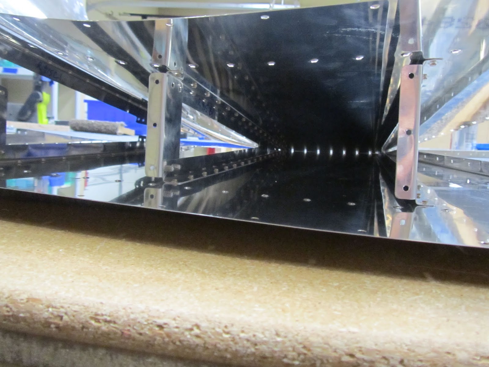
 Figuring out that the holes didn't line up... Also, a great view of the hole that you have to fit a bucking bar into.
Now you can see the bottom "tab" sitting flush 
 Cleco until you are blue in the face.

Now, after we know it all fits together, it all gets taken apart, after drilling the holes to size. Then it gets deburred, and dimpled. It sounds simple, but the skin is .016" thick, and it seems like you are working with tin foil. 
 The only way I could keep from going too deep was twisting the deburring tool between my fingers. After hundreds of holes, I got a bruised thumb, but the work turned out awesome. You can just see the chamfer in the hole to the left of my tool.
Dimples for the skin. Super straightforward. This DRD2 tool produces excellent consistent results. 

Now, this is the first part of the build I will bag on Van's just a bit. The trailing edge "wedge" design on the rudder is poorly conceived, at best. You install a double countersink on a piece of angled extrusion. Then, you dimple the skins on either side, and rivet the whole works together. It's almost impossible to achieve a straight trailing edge.

All the angled squeezers I have seen end up putting marks in the skin.  The results are just not attractive. As for the bucking method spelled out by Van's in the instructions, I am extremely good at working with my hands, and careful with the rivet gun. Even using a 2X gun, on low pressure, its impossible to end up with a nice trailing edge on the rudder.

I have considered rebuilding the rudder, except on the new rudder, using structural adhesive just on the trailing edge. Heck, if its strong enough for Grumman to use in the wings, its strong enough for the trailing edge of a rudder....

Anyways, these pics show how you set up your drill press to do the countersinks. There is a length of that extrusion below the top portion, so the angle is correct.


Friday, September 6, 2019

Rudder 2...

Ok, so now we arrive at "dimple-pallooza"... Full disclosure: I ordered some kung-fu special tool for this procedure. I know that aircraft manufacturers have been using dimples for decades, but recently, a tool has been improved.

Recently, aircraft tool supply came out with a dimple die that makes substructure dimples fit much better. I bought a set, and the results are amazing. The windup is that the skins receive a regular dimple, and anything connected to the skin, receives a slightly deeper dimple to make it fit perfect...


The net result is nothing less than perfection..


Rudder 1

The rudder turned out to be the most challenging assembly so far. I know it will bet much more difficult, but the rudder was tough for a couple of different reasons. First, the rudder skin is only .016" thickness. That is ridiculously thin. The only real trouble area was the trailing edge. What a pain. Second; the rudder trailing edge: I am SERIOUSLY considering a different technique for the rudder trailing edge. IMHO, the van's approach is flawed. I will talk about that later...

Anywhoo....I will tell the story in how it was assembled. Honestly, this part is great engineering. First, you build the rudder spar. this was fairly easy, you add a couple of doubler plates, and rivet on some nut plates. The rib at the top houses the counterbalance weight. I was rather surprised how soon that rib was added to the spar, but it made sense later.  I alodined the parts I could fit in my "dip buckets".

The counterbalance rib was where I made a small mistake. I will illustrate that more later...


Better shots of the rudder horn, and the doublers. Note that I like to label the parts. It makes it easier for me to keep this stuff straight. Once you see the instructions, you will see why this makes sense. Well, to me anyways. I found that making some makeshift clamping devices, makes things so much easier. This is what I built. You might find something more efficient, but this worked for me!


Gratuitous diet coke shot here... The mistake is apparent in the counterbalance rib in this pic, but I will discuss later...


Eventually, the instructions lead you to this skeleton. You cleco it all together and match drill everything. You rivet the rudder horn at this time. Not gonna lie, I was kinda nervous riveting that assembly (the rudder horn...). It's very thick. But it all worked out. 


Once completed... (check out those sweet-ass new balance tennies!!) Pay no mind to the rivet on the left hand side of the nutplate. On the back side of the rudder horn, that rivet holds a zip-tie anchor that will eventually hold a nav-light wire?


As we progress.... The plans have you cleco the skins and the stiffeners to the assembly. Next, you match drill till you are blue in the face. On the serious, I am super proficient at drilling a hole, while holding a pair of cleco pliers, and a drill, in the same hand.... (trust me, it makes sense when you see it in person....


So, this is where things got slightly interesting. This little "R910" part, just didn't fit correctly. It took quite a bit of massaging to make it fit right. You can force parts into position with cleco's, but they will be a pain in the ass to rivet later when the clecos are removed. Initially, I thought the 910 was causing some of the "oil-canning" of the skins, while it was all cleco'd up. So I massaged it all into place so it fit right. The devil is in the details. I have found so far it is fits without forcing, your life gets a lot easier....


This was the gap I was trying to eliminate... (Between the vertical part on the right, and the horizontal 910 piece...)


The gap between the rudder horn (on the right) and the 910 piece. Eventually I just use a pair of seaming pliers to bend it all into position, and it helped. I'm glad I did this, because riveting this all together was really tough a little bit later...

To be continued.......